Why Following Quality PV Design is Key to Long-Term Performance (part 1)

By Pijus Sciuckas, Design Engineer at Detra Solar.
Introduction
As solar parks reach their fifth or tenth years of operation, two similar capacity sites with the same initial investments but opposite approaches can have drastically different OPEX outlooks.
One of the key areas where these outlooks diverge is the waltz between design and construction, where precision dances with execution.
While niche construction solutions always have a place in our competitive global industry, our focus today is on poor execution practices that stem from a “get it done ASAP” mentality rather than a “get it done well” commitment.
Ultimately, this issue centers on critical design points that later on get treated as mere “suggestions” or a part of the scope to consider cutting to save on time and budget. It’s what leading industry subject matter expert Andreas Bach aptly calls: Silent Yield Killers.
Silent Yield Killers – Design VS Construction
I would like to expand on how Mr. Bach categorizes these, if you will, SYK’s. They start with development and design, later on procurement, construction and finally commissioning. As I mentioned above, today’s focus is design and the divergence from it during construction.
I will tackle the most common issues stemming from:
- Cables, their routing, and connectors;
- Consequences of bad drainage design (or the lack of it);
- Equipment placement;
- General bad layout optimizations.
All examples taken from our site visits to on-going projects, i.e. in-field observations, comments from the managing O&M teams.
1. Cables, Routing, and Connectors
Cables and their connectors are prime suspects for overbooked O&M teams, whether from insufficient crimping forces applied or from freely hanging cables that over time lose their insulation by brushing against sharp construction edges.
The former can be avoided by ensuring that the DC installer uses certified tools and references all related installation manuals; while the latter is a simple question of fastening. Although, is it really that simple? Let’s dive deeper and see how different developers tackle these solutions.
Cable Fastening
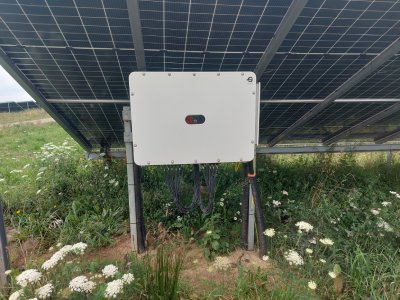
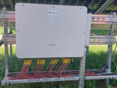
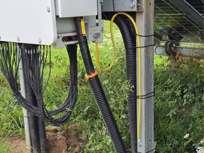
From a design perspective, we always advise to never leave cables hanging. This subject is a bit broader than just zip ties and involves considerations I will mention later in the article, so expect some overlap. Nonetheless, this relation matrix is a good example of how each design decision dictates the ones in front of it and eventually the end cost of the asset.
For example, on the right side you can see two ways of mounting an inverter under a fixed tilt construction. Even though the top one is from Huawei and the bottom one Sungrow, the general cable installation rules are all identical for both:
|
 |
|
 |
|
 |
While connection terminals are well known to cause headaches, we must explore the universal handyman’s tool: the zip tie. There is no denying that they are cheap, lightweight, and easy to install. But we cannot forget that plastic is not meant to be under tension for decades, exposed to UV rays, rain, and frost.
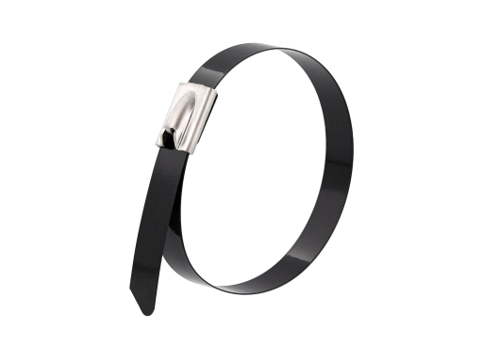
When zip ties start turning brittle and falling to the ground due to the cable weight they are holding, an O&M team has to spend weeks going through the whole site, replacing each fastener. Is there really no better way? Here are two examples:
|
 |
|
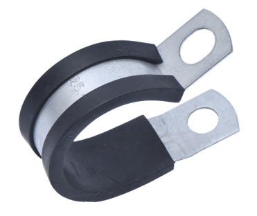 |
Naturally, there are countless better options to replace zip ties. And all of them should be diligently explored, whether for bundling cables together or for cable routing.
Cable Routing
This topic refers to cables around PV frames, i.e. ways of routing that ensure their longevity. I have already touched on excess cable tension originating from loose cables, a problem tackled with various kinds of fasteners. Following that, the next step is to decide if those cables should be housed in ducts, where and for what purpose.
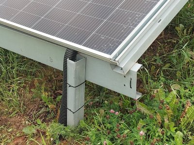
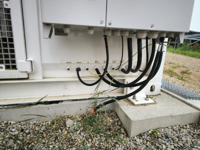
The most significant reasons to use ducts under and between frames are: sharp edges; exposed purlin (‘C’ shaped beams) pathways or exposed areas in general; threats from animals and lawnmowers.
Sharp Edges
Structural sharp edges – often overlooked during the initial design phase – act as one of the most persistent, silent threats to cable integrity. When DC or AC cables are routed across unshielded purlins or frame vertices, vibration from wind and thermal expansion gradually cuts into cable insulation. Over time, these micro-abrasions lead to insulation failure, earth faults, and potentially catastrophic string shutdowns.
As mentioned before, other problems can come from ducts being too exposed at ground level, causing risk of being chewed off by animals or cut by lawnmowers. See below:
 |
 |
As for sharp edges, to mitigate this, design must account for “edge management” as a core component of the cable routing plan. This includes:
|
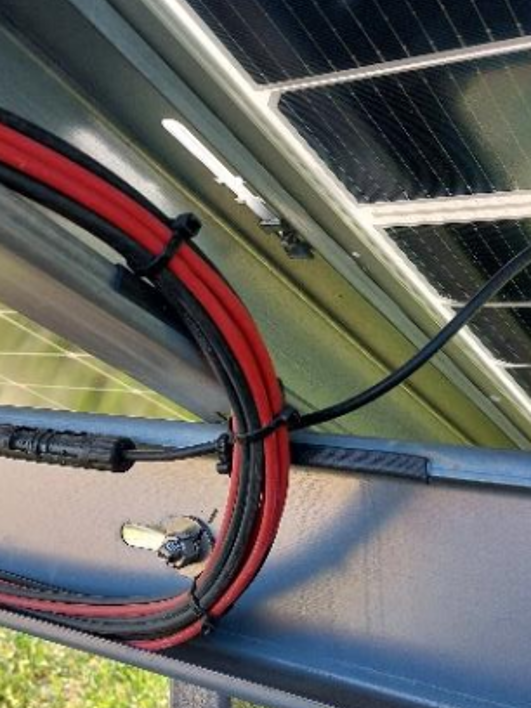 |
Ultimately, addressing sharp edges is not merely a “best practice” – it is a critical reliability measure that prevents localized electrical failures from escalating into long-term site degradation.
Cable Connectors
Ensuring Connector Integrity
While the MC4 connector is the industry standard for PV installations, it remains a frequent point of failure for projects that prioritize speed over precision. A robust connection requires more than just a physical click; it demands strict adherence to engineering specifications to prevent long-term electrical degradation.
- The Mismatch Fallacy: It is critical to use the exact same brand and series of connectors as those factory-installed on the PV modules. Mixing brands – even when they appear mechanically compatible – leads to improper sealing and poor electrical contact, creating “Silent Yield Killers” that cause thermal hotspots and water ingress over time.
- Precision Crimping: There is no substitute for using the manufacturer-specified crimping tool. Relying on “universal” tools often results in inconsistent crimping forces or damaged pins. Every installer must strictly reference the connector manufacturer’s manual for exact strip lengths, insertion depths, and torque requirements to ensure a gas-tight electrical bond.
A failure to follow these protocols does not just risk a single string; it compromises the entire site’s operational longevity, leading to arcing, intermittent disconnections, and, in worst-case scenarios, fire hazards. Proper assembly is a non-negotiable prerequisite for any reliable PV asset.
Ultimately, bridging the gap between design precision and field execution isn’t about adding unnecessary costs – it’s about protecting your asset’s long-term return on investment. By treating design parameters as strict rules rather than mere suggestions, developers and EPCs can eliminate these Silent Yield Killers before they ever manifest in the field, ensuring that an asset built today continues to perform reliably for decades to come.
Coming Up in Part 2: Drainage Design Flaws & Soil Stability
Ground level is where some of the most expensive “Silent Yield Killers” hide. In Part 2, we will shift our focus to Consequences of Drainage Design Flaws. We’ll examine how poor water management leads to severe soil erosion and site flooding, and highlight real-world standard-setting practices – from utilizing sprayable grass technology to reinforce root systems, to strategic melioration ditching that keeps critical infrastructure dry. Stay tuned!