Owner’s Engineering in Action: Resolving Critical Design Issues Mid-Construction

Designing and building solar PV systems requires precision, compliance, and continuous validation. But what happens when construction is already underway, and questions start surfacing about cable routing, overvoltage, or stringing practices?
What started as a request to review DC stringing quickly evolved into something much broader. The client initially brought us in to validate their Solar project. But as more site challenges emerged—including concerns around voltage drop, cable routing, and installation quality—they needed deeper technical support.
This case highlights how Owner’s Engineering can adapt in real time—offering not just issue resolution, but forward-looking technical guidance. From stringing validation to full-system compliance checks, we break down the process and decisions that helped move the project toward safe, high-performance delivery.
Key Areas of Review
The scope of the technical assessment included:
- Reviewing and optimizing the DC stringing design
- Providing guidance on DC isolation and protection, including inline fuses and rotary isolators
- Updating and validating the PVsyst model to match design changes
- Responding to contractor technical queries on wiring methods, voltage drop, containment, and more
- Ensuring proper labelling of PV equipment and verifying accuracy of as-built documentation for effective O&M and compliance
- Verifying compliance with British Standards (BS), IET Codes, IEC standards, and project-specific norms
Let’s explore the most instructive takeaways.
1. Cable Routing: The Hidden Risk of Inductive Loops and Lightning
Initial installation featured multiple inductive loops in array cables—posing risks under certain fault or lightning conditions. Although often overlooked, these configurations can increase electromagnetic exposure and compromise surge protection strategies.
Such loops typically form when DC cables are routed with excess slack or in curved, circular paths instead of following clean, parallel runs. This can unintentionally create inductive loops that behave like antennae—amplifying interference and increasing vulnerability to transient overvoltages.
Action taken:
The team assessed the installation against the IET Code of Practice for Grid-connected PV Systems and provided a detailed risk assessment, offering corrective routing guidance to eliminate unnecessary loops and reduce exposure.
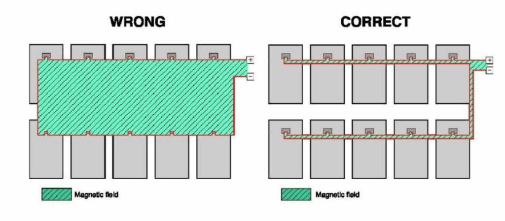
Image 1: Loop formation explanation as shown in the design drawings
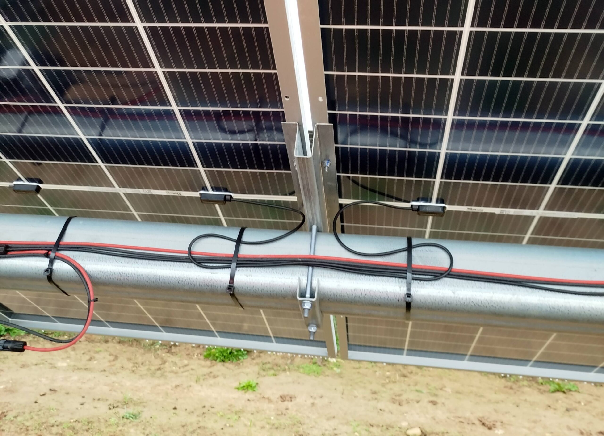
Image 2: Real-world cable runway
🔍 How this can be covered:
- Electrical Design Review, Regulatory & Standards Compliance, and Design Risk Assessment Review
- Output: Commented drawings, risk commentary, flagged compliance deviations
2. Voltage Drop: When 1% Isn’t Always the Right Benchmark
Guidance in the IET Code of Practice recommends a 1% voltage drop between the point of supply and inverter—for domestic systems. However, in larger-scale or more complex layouts, especially those with extended cable runs, voltage drops of 2–4% may be justifiable.
In this project, the measured voltage drop across LV AC circuits ranged from 1% to as high as 5%, triggering the need for detailed review.
Our response:
We conducted a detailed review of the LV cable design and inverter layout, supported by simulations using ETAP — an industry-standard electrical power system analysis platform. ETAP allowed for accurate modelling of electrical networks, enabling us to validate voltage drops under real-world operating scenarios and identify areas for refinement.
Where relevant, we advised on equipment placement, cable sizing, and routing to align with best practices and strike the right balance between efficiency, cost, and compliance.
🔍 How this can be covered:
- Electrical Design Review, Optimization for Cost, Efficiency & Risk, and Energy Yield Impact Analysis
- Output: Commented calculations, optimization report, yield sensitivity insight
3. Cable Containment & Segregation: More Than Just a Tidy Job
The project featured mixed-use of cable trays and containment systems for DC, AC, and communication services. While segregation was provided for communications cables, AC and DC cable proximity in some areas fell below recommended distances.
Risk assessment included:
- Confirming compliance with BS 7671 and relevant European norms
- Reviewing containment materials, spacing, and installation techniques
- Recommending solutions to ensure proper segregation and safety clearance
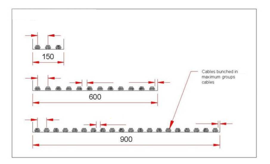
Image 3: Cable trays in the design drawings
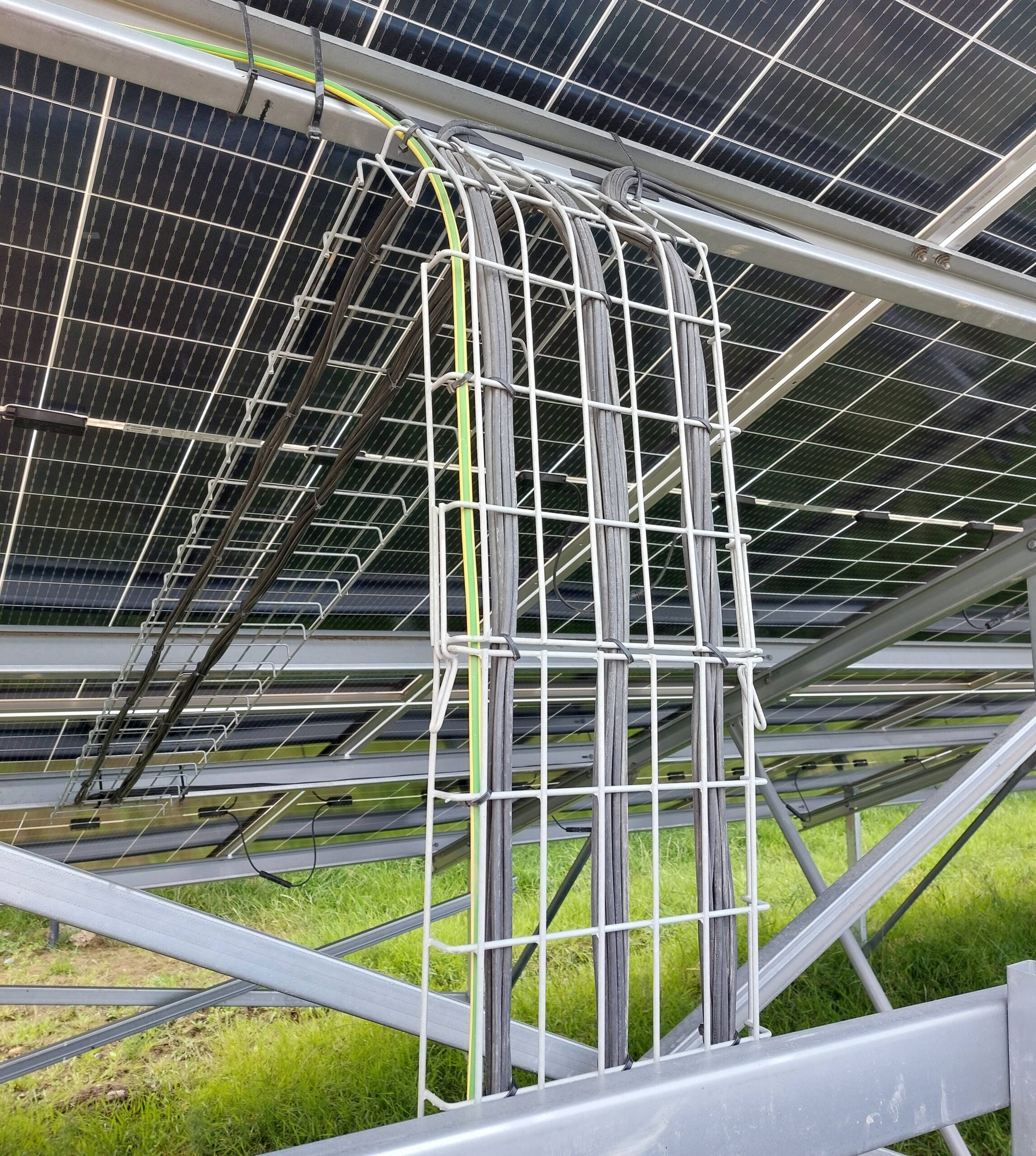
Image 4: Real-world cable separation
🔍 How this can be covered:
- Constructability Review, Regulatory & Standards Compliance, and Electrical Design Compatibility
- Output: Optimization and constructability report with corrective layout suggestions
4. DC Cabling Between PV Panels: When Simplicity Needs Safeguards
Cable ties and standard MC4 connectors were used between modules to manage strings (PV modules connected in series) and reduce exposure. However, mechanical protection was lacking at high-level installs under the canopy, increasing the risk of wear or damage over time.
Recommendation:
Reinforce exposed cable runs with mechanical protection or reroute connectors into shielded areas—accompanied by design risk documentation and layout sketches.
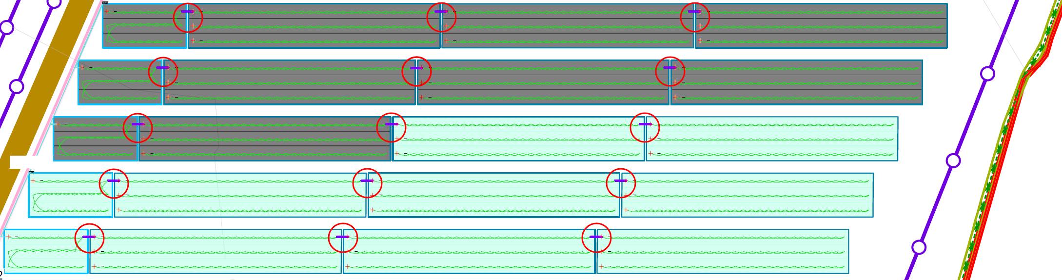
Image 5: Reinforce cable runs in the design drawings
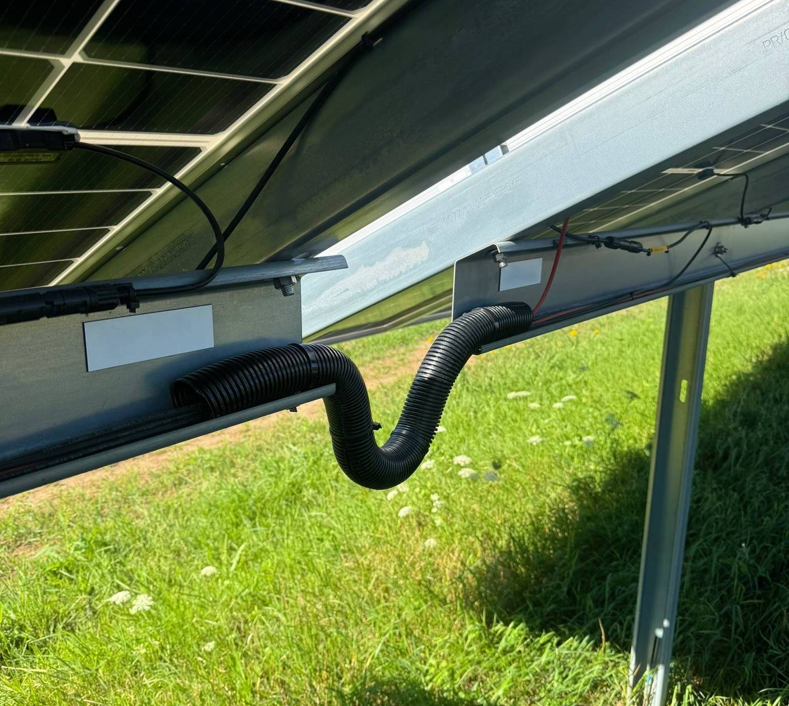
Image 6: Real-world Reinforce cable runs
🔍 How this can be covered:
- Interface & Constructability Review and Design Risk Assessment Review
- Output: Commented risk document and installability recommendations
5. Earthing Through Module Fixings: Acceptable or At Risk?
In this project, PV modules were secured to the canopy structure using zinc-plated bolts, with the structure itself earthed. While this is a commonly used practice, it doesn’t automatically ensure a compliant or enduring earthing path—especially under long-term exposure or in corrosive environments.
Why it matters:
Reliable module bonding is essential for electrical safety, proper fault clearance, and lightning protection. If the mechanical fixings lose conductivity due to corrosion, thermal cycling, or poor contact, it may lead to increased system risk and non-compliance with standards such as BS 7671 or IEC 62548.
What we reviewed:
As part of our design verification, we assessed whether the implemented earthing method:
- Provided a suitable scheme for equipotential bonding using standard grounding hardware
- Recommended grounding conductors with resistance values below 1 Ω
- Was properly documented in earthing diagrams and single-line schematics
- Aligned with relevant industry standards and manufacturer installation manuals
Where necessary, we provided a design risk commentary and advised whether supplementary earthing methods—such as bonding jumpers or corrosion-resistant fasteners—should be considered to enhance long-term performance.
🔍 How this can be covered:
- Regulatory & Standards Compliance, Electrical Design Review, and Design Risk Assessment
- Output: Risk commentary and earthing recommendations based on observed implementation
6. PVsyst Update: Reflecting Reality in Performance Modelling
Even minor updates to PV table layout or module power can impact simulated energy yield. In this case, Detra Solar re-ran the PVsyst model to reflect:
- Revised stringing schemes
- Updated table positioning according to the topography
- Shading loss evaluation using a refined 3D site model, including OHL pylons, vegetation, and nearby obstructions
This helps ensure that performance estimates align with actual installation—an essential step for investor confidence and grid planning.
🔍 How this can be covered:
- Energy Yield Impact Analysis
- Output: Updated Yield Optimization Report
7. Marking and Documentation: Why Labelling and As-Built Drawings Matter
Clear labelling of PV equipment and comprehensive as-built documentation are often treated as final checklist items—but their role in long-term operations shouldn’t be underestimated.
What we observed:
In this project, inconsistencies were noted in the labelling of combiner boxes, DC string identification, and inverter feeds. While functionally minor during construction, unclear or incomplete labels can become major hurdles during maintenance or fault tracing.
Our approach:
As part of our verification, we also recommended updates to the as-built electrical drawings to reflect the final field implementation, ensuring one-to-one correspondence between on-site components and documentation.
Why it matters:
Correct labelling and well-maintained drawings are essential for safe, efficient, and cost-effective operation and maintenance (O&M). They help reduce downtime, prevent errors during inspections or repairs, and simplify onboarding for new maintenance teams. For asset owners and operators, this translates into better system visibility, lower service costs, and stronger lifecycle performance.
🔍 How this can be covered:
Part of: Design Risk Assessment
Output: Commented mark-up of existing drawings, documentation improvement notes
Our Broader Role in Utility-Scale Projects
Since we provide design services across the full solar project lifecycle, our team brings first-hand insight into both the technical depth and practical realities of solar development. That perspective shaped our approach—going beyond issue identification to help guide the project toward durable, compliant, and performance-driven outcomes.
This technical verification was part of a larger framework of support we provide across the project lifecycle, including:
- Feasibility & Pre-Construction Support: Site assessment, grid feasibility, capex/opex analysis
- Design Review & Optimization: Reviewing EPC designs for compliance and performance
- Tendering Support: Technical input during procurement to align with budget and specs
- Quality Assurance: Inspection protocols, milestone verification, and NCR management
- Project Oversight: Reporting, coordination, and timeline control
- Risk Management & Technical Advisory: Identifying challenges early and guiding resolutions
- Commissioning & Handover: Reviewing performance tests and verifying documentation
✅ The Takeaway: Proactive Design Validation is Non-Negotiable
As this project shows, design verification is not a one-time checkbox—it’s a continuous process that often needs to expand as real-world challenges surface. From stringing adjustments to installation checks and compliance reviews, having a flexible technical partner on board helps de-risk the project as it moves forward.
Whether you’re dealing with complex builds or just want confidence in your PV or storage system, independent verification and expert insight can make all the difference.
Need adaptable Owner’s Engineering support?
We help EPCs and developers stay ahead of design risks, installation issues, and regulatory gaps—across Europe and beyond.
Get in touch with our team to make sure your project meets the standards—with no surprises down the line.
👉 Learn more about our Owner’s Engineering service.